

Electric Ductile Iron Lug Butterfly Valve Single Clamp Supporting Ear
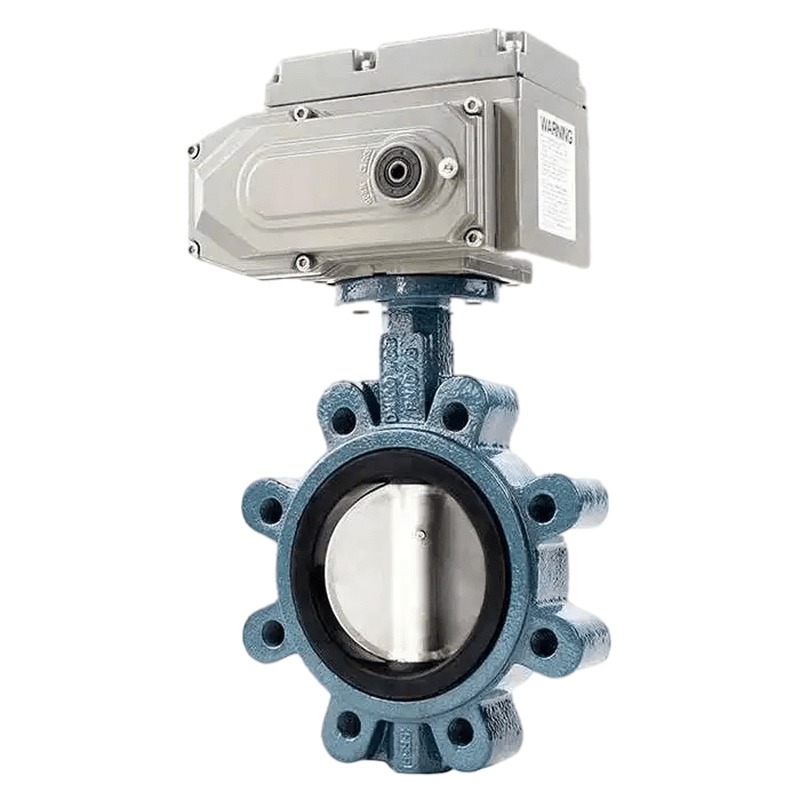
The electric ductile iron lug butterfly valve with single clamp supporting ear is a quarter-turn pipeline control valve that pairs a compact electric actuator with a centerline resilient-seated lug body. Manufactured by Trekre & Fouten Valve at our Wuxi factory, this electric lug butterfly valve is designed for remote on-off or modulating duty in water supply, HVAC, municipal distribution, light industrial process lines and building automation circuits where ductile iron construction and lug-type bolting are specified on the valve schedule. The single clamp supporting ear lug pattern allows the valve to be held between companion flanges with through-bolts passing through each lug ear, so downstream piping can be removed for maintenance without disturbing the upstream flange joint.
Compared with a manual lug butterfly valve on the same nominal size, the electric actuator delivers repeatable remote switching, position feedback and scheduled cycling where operators cannot reach a handwheel on every shift. Compared with wafer-type electric butterfly valves, the lug body retains individual bolt paths through each ear so sectional isolation and downstream spool removal remain practical on process branches and packaged skids. Compared with stainless steel electric lug valves on the same line class, ductile iron QT450-10 or GGG50 body construction offers a cost-effective pressure boundary for clean water, air, chilled water and mildly corrosive utility media within the temperature and chemical limits of the selected seat material.
Structure and working principle
The valve follows a centerline butterfly pattern with a disc rotating 90 degrees around a stem supported by internal bearings, a lower bushing and a stem packing gland on the bonnet. Lug ears cast into the valve body accept through-bolts that engage companion flanges on each side of the installation. The single clamp supporting ear designation refers to the lug geometry that supports clamp-style installation between flanges while maintaining the structural ears required for lug bolting patterns on ANSI, DIN, JIS or EN companion flanges as stated on the purchase order.
When the electric actuator receives an open or close command, the motor drives the stem through a gear train or direct quarter-turn output, turning the disc from parallel to perpendicular relative to the flow bore. At full closure the disc face compresses the resilient seat ring—typically EPDM, NBR or VITON depending on medium and temperature—to establish the primary seal boundary. The top flange on the valve bonnet complies with ISO 5211, allowing standard electric actuators, handwheel overrides or future drive upgrades to mount without adapter plates beyond those specified on the datasheet.
Stem seals combine V-ring or O-ring packing above the upper bearing to limit external leakage during thermal cycling. Electric actuators supplied with this valve class are sized against calculated breakaway and running torque for the stated differential pressure, seat material and valve size. On-off actuators use open and close limit switches to confirm end position. Modulating actuators accept 4–20 mA or 0–10 V control signals when the disc geometry and seat construction suit throttling duty within the stroke range defined on the project datasheet.
Nominal size and pressure class
Standard production covers nominal diameters from DN50 to DN600 (NPS 2 to 24) with intermediate sizes available on request. Pressure ratings commonly include EN PN10 and PN16, JIS 10K, and ANSI Class 150 lug configurations. Face-to-face dimensions follow manufacturer tables for lug butterfly valves or project-specific requirements when a non-standard length is mandated. Flange connection hole patterns can be supplied to United States ANSI B16.5, European EN 1092, German DIN, Japanese JIS and other regional standards as stated on the purchase order. Confirm companion flange rating, gasket type and bolt length before installation so the lug ears and through-bolts carry the design load without distortion.
Body, disc and seat materials
The primary pressure boundary uses ductile iron QT450-10 or GGG50 for the body when the project calls for general water, air and HVAC service within the cast iron temperature range. The disc is typically ductile iron with nickel-plated or nylon-coated wetted face, or stainless steel 304/316 when the medium specification requires upgraded disc corrosion resistance. Seat materials commonly include EPDM for potable water, chilled water and HVAC loops; NBR for oil-bearing air or light hydrocarbon contact; and VITON (FKM) where higher temperature or selected solvent contact is defined on the datasheet. Seat selection must match the actual medium, operating temperature and cleaning procedure because elastomer limits are not interchangeable across products.
Sealing form and leakage performance
Primary sealing relies on compression between the disc face and the resilient seat ring at full closure. Lug-type installation does not change the seat mechanics compared with wafer designs; the bolting arrangement only affects how the valve is held between companion flanges. Closure leakage is verified by seat test per the agreed project protocol and manufacturer test procedure. State the required leakage class or test medium in the purchase specification rather than assuming a universal rating across all sizes and seat materials.
Electric actuation and control options
Electric actuator form includes switch type for two-position isolation and adjustable (modulating) type for proportional flow control when valve construction supports throttling. Supply voltage options include DC 24 V, AC 110 V, AC 220 V single-phase and AC 380 V three-phase depending on actuator model and motor class. Control inputs for modulating duty typically accept 4–20 mA or 0–10 V analog signals. Optional RS485 communication can be equipped when the instrument specification requires fieldbus integration with PLC or DCS systems.
Opening and closing stroke times depend on actuator output speed, gear ratio and actual torque load during the stroke; specify required stroke time on the datasheet for factory verification. Fail-safe behaviour on power loss—remain in last position, spring return to open or spring return to close—must be defined in the instrument specification because actuator models differ. Motor thermal protection, position indication on the local actuator cover and junction box entries for field wiring are configured according to the area classification and cable gland standard stated on the electrical drawing.
Applicable working conditions and industries
This electric ductile iron lug butterfly valve is specified on municipal water distribution branches, HVAC chilled and hot water loops, fire protection utility headers where electric remote operation is required, building automation sequences, irrigation mains and light industrial process water lines. The lug connection suits applications where downstream piping must be removable for pump or filter maintenance while upstream equipment remains connected. Electric operation fits remote valve stations, plant rooms and automated sequences where manual access is limited or where integration with BMS, PLC or SCADA panels is mandatory.
Standards, inspection and delivery
Design and inspection commonly reference EN 593, MSS SP-67, API 609 or GB/T 12238 depending on the project region. The valve body top flange complies with ISO 5211 for interchangeability with standard electric actuators. Each valve undergoes shell pressure test and seat closure check before shipment. Functional actuator tests, dimensional reports and material certificates can be included in the QA dossier when requested. Valves are cleaned, flange-faced protected and packed for export from Wuxi. Trekre & Fouten Valve engineers can review your medium composition, pressure-temperature profile, control signal type and flange standard to confirm body grade, seat selection and actuator class.
Product parameters
| Valve type | Electric ductile iron lug butterfly valve, single clamp supporting ear |
| Structure | Lug type, centerline resilient seated |
| Size range | DN50 – DN600 (NPS 2 – 24); larger by quotation |
| Pressure rating | PN10, PN16; JIS 10K; ANSI Class 150 (as specified) |
| Body material | Ductile iron QT450-10 / GGG50 |
| Disc material | Ductile iron nickel-plated or nylon-coated; stainless steel optional |
| Seat material | EPDM, NBR, VITON (FKM) (as specified) |
| Connection | Lug type; single clamp supporting ear; DIN, JIS, ANSI, EN (as specified) |
| Operation | Electric actuator; on-off or modulating (4–20 mA / 0–10 V) |
| Supply voltage | DC24V, AC110V, AC220V, AC380V (as specified) |
| Top flange | ISO 5211 actuator mounting |
| Design standard | EN 593, MSS SP-67, API 609, GB/T 12238 (as agreed) |
| Test | Shell and seat test per project specification |
Selection notes
Specify flange standard and pressure class, body and seat material, operating temperature and medium composition, available supply voltage, control signal and required stroke time. Confirm whether the duty is strict isolation or includes modulating throttling so the correct seat and actuator type are paired. State enclosure rating and area classification for the actuator and junction box. Allow clearance for actuator height, handwheel override access and maintenance space around both lug bolt circles. When RS485 or other fieldbus communication is required, include protocol details on the instrument datasheet.
Installation and maintenance guidance
Install the lug valve between companion flanges with gaskets suited to the medium and flange class. Tighten through-bolts in a cross pattern so lug ears load evenly without bending the body. Mount the electric actuator within orientation limits on the nameplate. Wire the actuator through the project MCC or local starter according to the electrical schematic. During commissioning, verify limit switch or transmitter feedback matches physical disc position through several open-close cycles under line pressure. Periodically inspect seat contact, stem packing and actuator heater operation in outdoor installations. Replace packing when external leakage appears during thermal cycling.
Comparison with adjacent designs
Manual lug butterfly valves on ductile iron bodies suit local operation but cannot support remote sequences. Wafer-type electric butterfly valves save length but do not offer the same downstream removal convenience through individual lug bolting. Pneumatic lug butterfly valves deliver faster stroke when plant air is available but require separate air treatment and may not suit sites without compressed air infrastructure. Stainless steel electric lug butterfly valves address higher corrosion resistance where ductile iron is excluded by the material specification. The electric ductile iron lug butterfly valve with single clamp supporting ear fits mid-bore water and HVAC branches where lug installation flexibility, ductile iron economy and motorised remote operation are all required on the same valve tag.
This electric ductile iron lug butterfly valve extends the Trekre & Fouten electric butterfly valve range for plant owners who need motorised isolation on lug connections with configurable seat materials and actuator control options. Contact our sales team with flange details, medium data, voltage requirement and control signal type for quotation and delivery schedule from our China valve manufacturing facility.