
Handle Ball Valves Manufacturers
VALVE Categories
The handle ball valve has a handle on the ball valve, the handle can be turned to control the ball core switch, the handle can be removed and stored separately
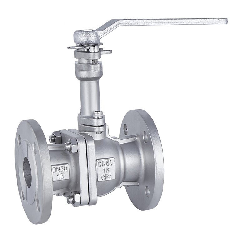
Stainless Steel Extended Rod Flange Ball Valve
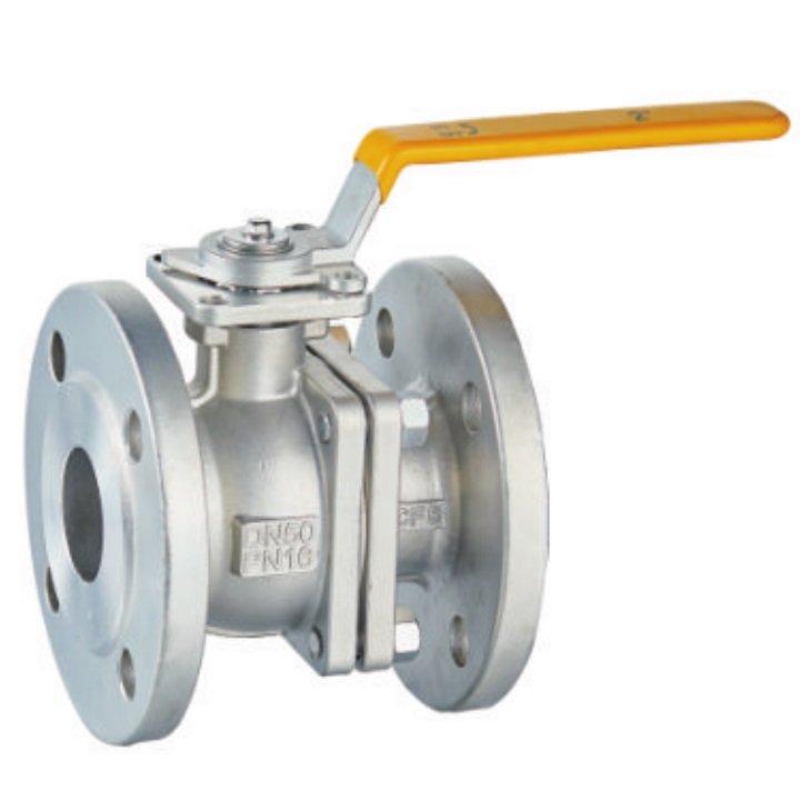
DIN Flange Ball Valve Full bore Stainless Steel

stainless steel Lined ball Valve PFA/FEP/PTFE

ANSI Class 300 Flanged Ball Valve Gear Operated/handle
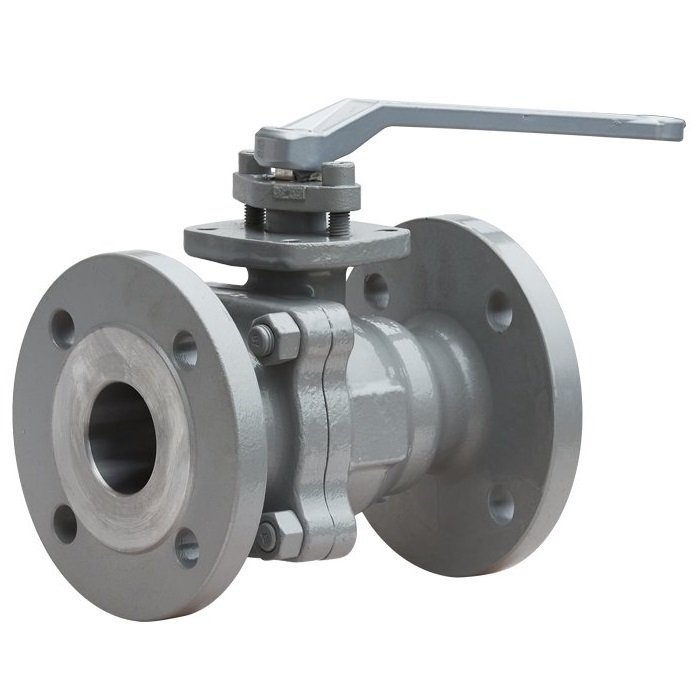
Metal Seated Flanged Ball Valve with ISO 5211 upper flange

ANSI class 600 ball valve Flanged
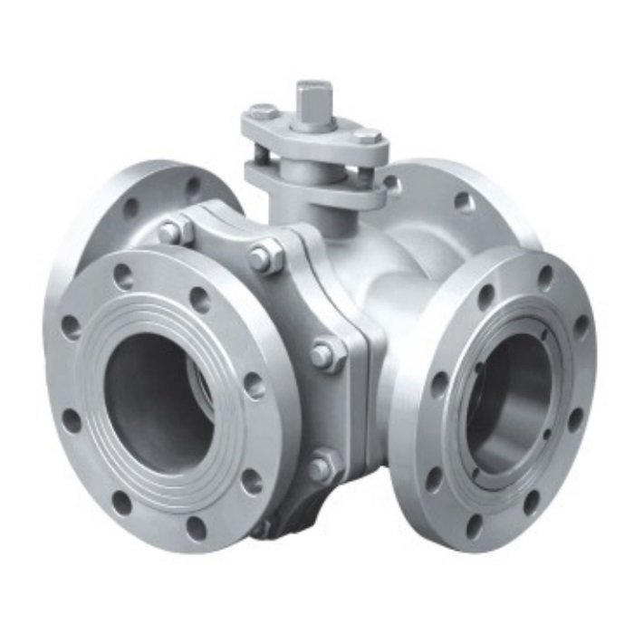
4-way flange ball valve Manufacturer-Stainless/Carbon Steel
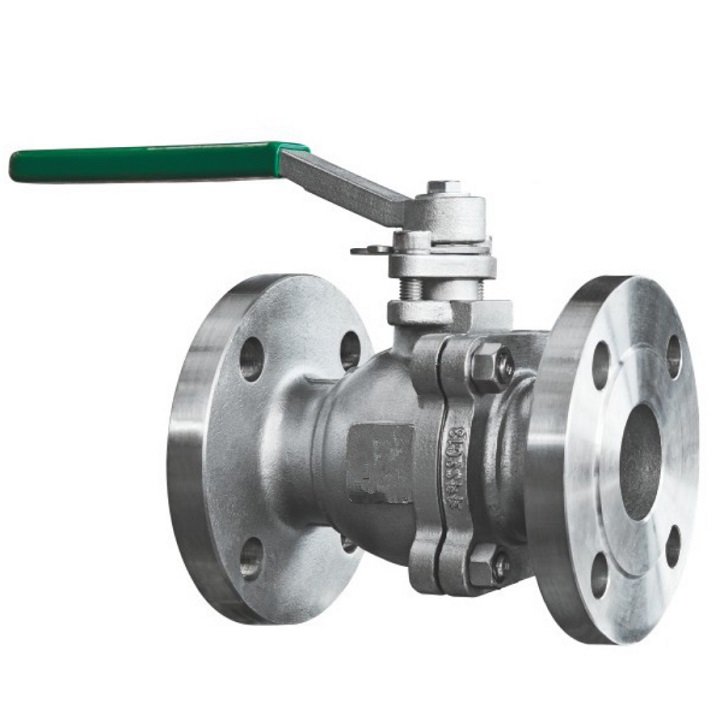
KS Flange Ball Valve – stainless steel manual handle
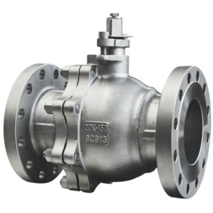
Flanged JIS 20K Ball Valve-stainless steel handle operation
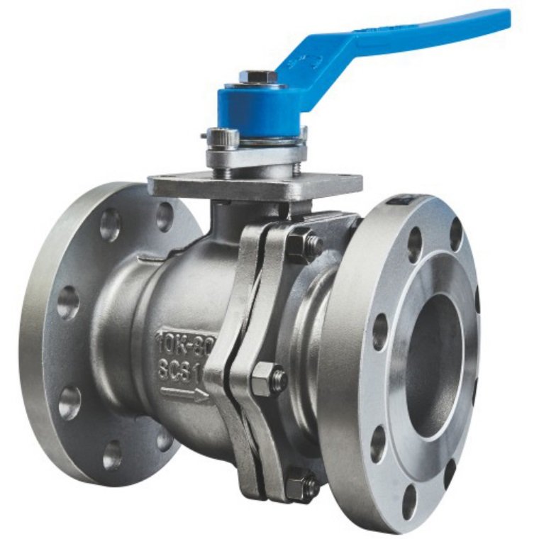
JIS 10K Flanged Ball Valve Stainless Steel/cast steel
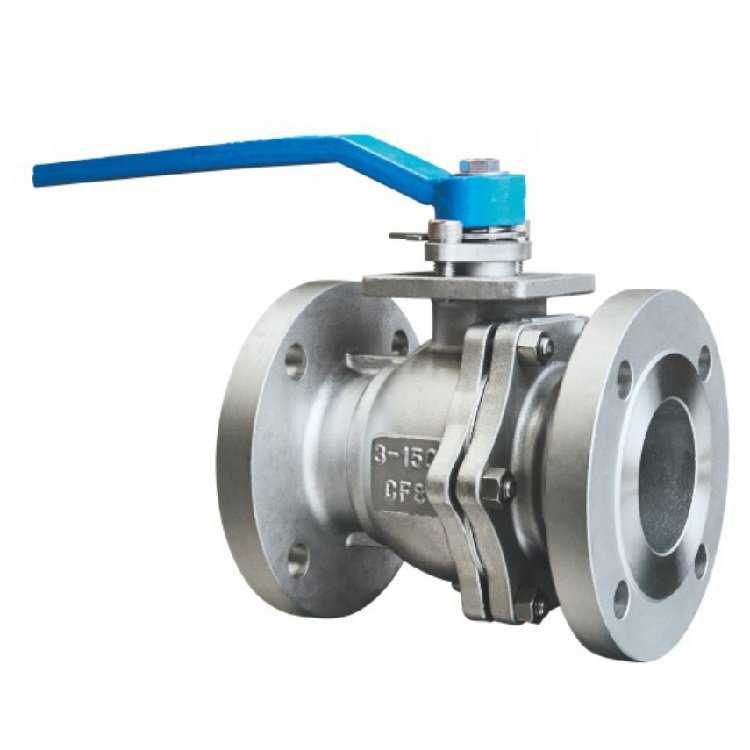
ANSI Class 150 Flanged Ball Valve
Trekre Handle Ball Valves Series
Manual Handle Ball Valve Operation
A conventional handle-operated ball valve uses a lever connected to the valve stem to rotate a ball with a flow passage. On a typical two-way quarter-turn valve, the lever moves the ball through approximately 90 degrees between the open and closed positions. The operating method is different from multi-turn rising-stem or orbit-style valve mechanisms.
The ball is supported and sealed by the selected valve’s seat and stem arrangement. A floating ball valve and a trunnion-mounted ball valve distribute operating and pressure loads differently. The selected design determines the permissible differential pressure, seat loading and operating torque.
Available Manual Ball Valve Configurations
Handle ball valves may be supplied with flanged, threaded or other documented end connections, depending on the product. Stainless steel, carbon steel and lined constructions serve different material requirements. Some larger valves require a gearbox rather than a direct lever because operating torque increases with size, pressure and seat design.
A handle-operated two-way ball valve should not be described as automatically having the rising-stem, helical-groove and guide-pin operation found in specialized orbit-style designs.
Selection Factors
| Item | What to check |
|---|---|
| Valve bore | Full-bore or reduced-bore construction and required flow capacity |
| Body and trim | Compatibility with the actual process medium |
| Seat material | Pressure, temperature and shut-off requirements |
| Operating torque | Whether direct lever operation is practical |
| Connection | Flange, thread or approved fitting standard |
| Maintenance | Stem seals, seat access and required isolation procedure |
Installation and Operating Checks
Verify the correct valve orientation, pipe alignment and connection requirements before installation. Ensure sufficient clearance for full lever travel and safe operator access. During commissioning, check the indicated ball position against the actual flow path and inspect stem and body joints for leakage according to the approved test procedure.
Manual ball valves should be operated within their specified differential-pressure and torque limits. Applying additional leverage to a handle can overload the stem or seat mechanism. Compare ball valves, worm gear ball valves and electric ball valves where operating torque or remote actuation affects the selection.
Frequently Asked Questions
Can I use a hand lever, or should I specify a gearbox? Check the required operating torque under the specified size, pressure and seat conditions. A gearbox or powered actuator may be needed when direct lever operation is not practical. Do not use additional leverage on the handle to overcome torque beyond the valve’s specified limits.
Can I use a handle-operated ball valve for continuous throttling? Only where the particular ball, seat and operating arrangement is rated and selected for that duty. Many conventional ball valves are primarily intended for isolation; confirm the required differential pressure and operating conditions before selection.
What should I check before installing a manual ball valve? Verify the permitted orientation, pipe alignment and connection requirements. Leave clearance for full lever travel and operator access. During commissioning, check the indicated ball position against the actual flow path and inspect the stem and body joints according to the approved test procedure.