
Regulating Valves Manufacturers
VALVE Categories
Regulating Valves refers to valves that perform proportional switching of 4-20ma or 0-10V signals to the valve drive,manual valves can have an open scale

Pneumatic lined regulating valve Class150

Straight-through flange Pneumatic regulating valve

Pneumatic cage-regulating valve

Pneumatic flow regulating valve

Pneumatic flow cage-regulating valve
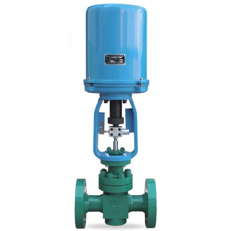
Electric Cage Sleeve Control Valve-axial flow labyrinth
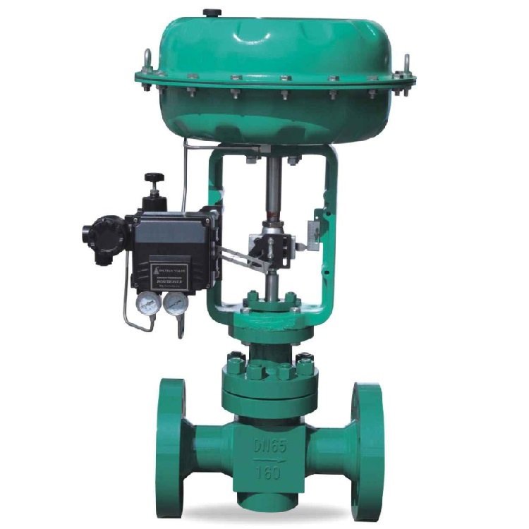
Pneumatic Cage Sleeve Control Valve-axial flow labyrinth
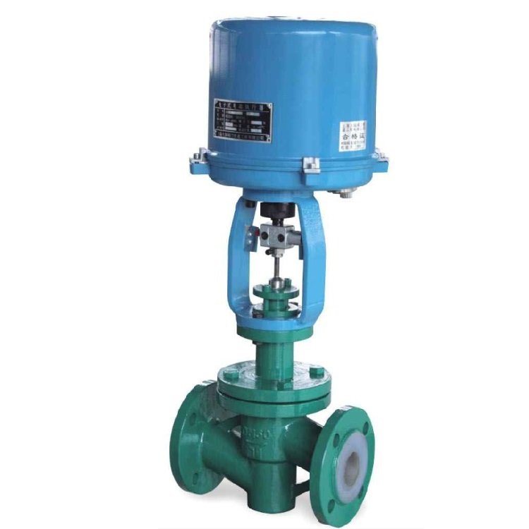
Electric lined control valve PFA/FEP/PTFE
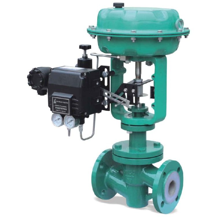
PFA PTFE FEP lined control valve Pneumatic Actuator
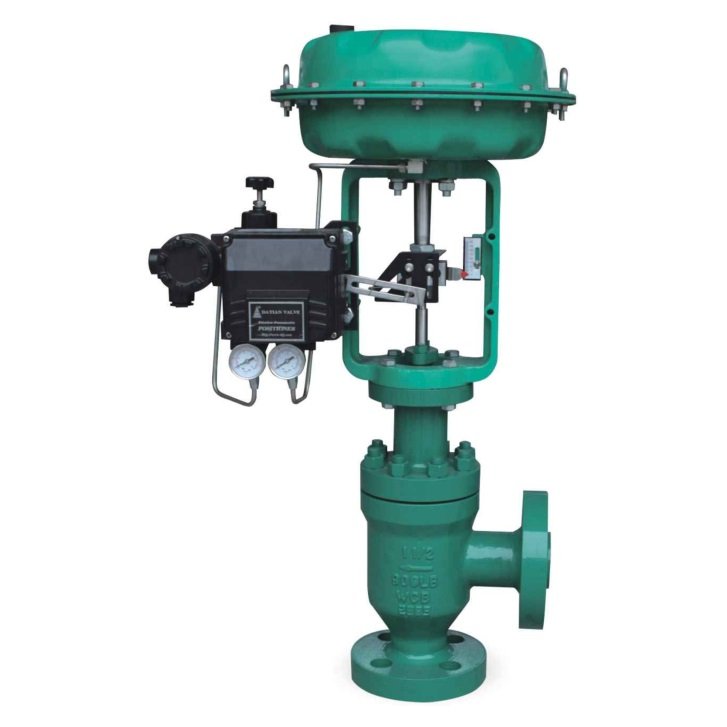
Pneumatic angle type control valve actuators Regulating

Electric angle control valve Electronic actuators Regulating
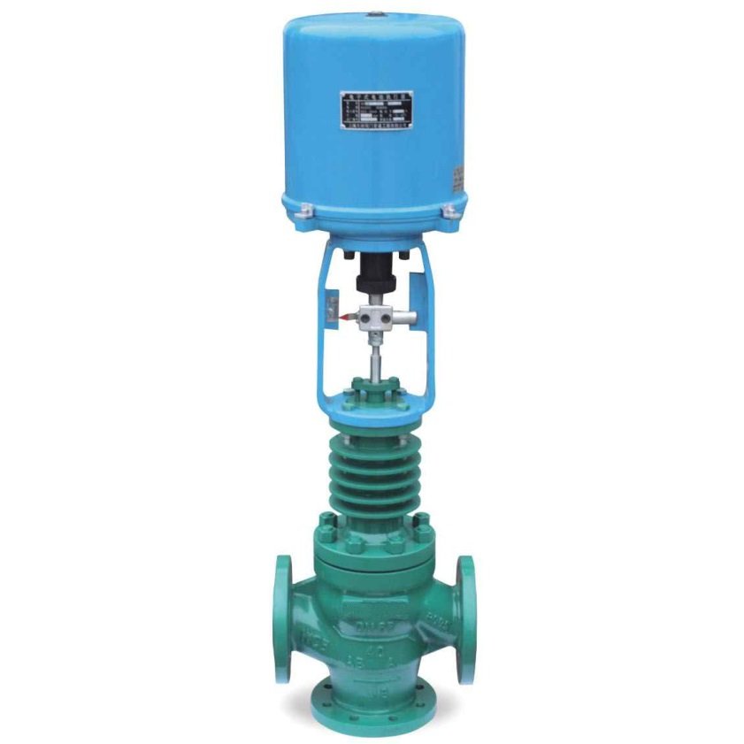
Electric 3-way regulating valve-diverter & confluence Valve
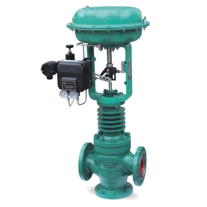
Pneumatic 3-way regulating valve-diverter & confluence Valve

Single Seat Globe Regulating Valve Electric/pneumatic
Trekre Regulating Valves Series
Regulating and Control Valve Selection
Regulating valves are final control elements that vary the flow of a process fluid in response to a control requirement. The valve body and trim create the flow restriction, while the actuator and control accessories position the closing member. A control valve may regulate flow, pressure, temperature or level as part of a correctly designed process-control loop.
Available control valve constructions
Control-valve construction depends on service conditions. Single-seat globe valves, cage-guided valves, angle valves and three-way diverting or mixing arrangements serve different hydraulic and process functions. Lined regulating valves provide a corrosion-resistant wetted barrier where the selected lining and trim are suitable for the medium.
Pneumatic actuators can be selected for modulating or on-off duties. Electric actuators are used where the specified torque or thrust, response time and control arrangement suit the application. A 4–20 mA signal or other command belongs to the installed control accessory and is not an inherent property of every regulating valve.
Key engineering inputs
| Input | Selection relevance |
|---|---|
| Minimum, normal and maximum flow | Valve size, operating opening and controllability |
| Inlet and outlet pressure | Differential pressure, actuator loading and trim suitability |
| Fluid temperature and composition | Body, trim, seat and lining selection |
| Required control characteristic | Trim design and installed response |
| Noise, cavitation or flashing risk | Special trim and process evaluation |
| Failure position and available utilities | Actuator and control-accessory configuration |
Selection and installation considerations
Control valves should be sized using the actual process range, required pressure drop and a suitable sizing method. An oversized valve may operate over a narrow portion of its useful travel, while an undersized valve may not pass the maximum required flow. Cavitation, flashing, noise, erosive solids and severe differential pressure can require special trim or an alternative valve construction.
For corrosive services, consider the complete wetted material path rather than the lining name alone. Installation should follow the selected valve’s flow direction, pipe support, straight-run and maintenance-access requirements.
Related options include pneumatic valves and electric valves.
Frequently Asked Questions
Do I need a modulating control valve or an on-off valve? Choose according to the process function. A regulating valve is selected to vary flow over a defined operating range, while an on-off valve is primarily selected to open or close the flow path. The valve trim, actuator and accessories must suit the required duty.
What process data should I provide for control-valve sizing? Provide the medium and composition, minimum, normal and maximum flow, inlet and outlet pressures, temperature and required control function. Include failure-position requirements, available utilities and any noise, cavitation, flashing or erosive-solids concerns so that sizing and trim suitability can be assessed.
Will the control valve work with my 4–20 mA control system? Confirm the positioner and control accessories specified for the valve assembly. The command and feedback signals belong to those accessories; a pneumatic actuator or regulating valve does not inherently provide a 4–20 mA interface.