
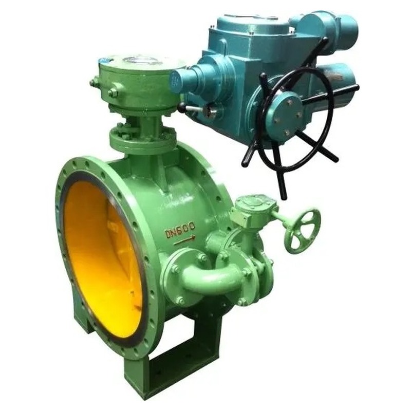

The electric flange butterfly valve with bypass valve is a double-flange isolation valve fitted with a small bypass branch on the disc outlet side and a motorised actuator for remote on-off or modulating duty on large-diameter headers. Manufactured by Trekre & Fouten Valve at our Wuxi factory, this electric butterfly valve addresses a practical torque problem on big bore lines: when the main disc closes against full line pressure, the differential across the seat can overload the electric actuator and extend stroke time. The integrated bypass allows controlled pressure equalisation across the main disc before the motor drives the full 90-degree opening or closing stroke, reducing actuator torque demand and improving overall system efficiency on pump discharge mains, cooling water headers, district heating branches and other high-flow utility circuits.
Compared with a standard electric double-flange butterfly valve without bypass, this configuration suits applications where operators must start or stop flow on large pipelines without subjecting the actuator to peak differential torque at the first degree of travel. Compared with manual gate valves with separate bypass loops fabricated in the field, the factory-integrated bypass butterfly branch reduces installation complexity and keeps the equalisation path within the valve envelope. Compared with pneumatic actuators on the same valve size, electric actuation supports direct DCS integration, position feedback and scheduled operation where plant air is limited or not available.
Structure and working principle
The valve body follows a double-flange pattern with raised or flat face flanges cast or fabricated as integral ends of the pressure boundary. The main disc rotates 90 degrees around a stem supported by internal bearings, a bottom bushing and a packing gland on the bonnet. In the centerline or double-eccentric layout specified for the order, the disc turns in the flow bore and compresses the seat ring at full closure. A bypass connection is arranged on the downstream side of the main disc flow path, fitted with a small manual butterfly valve (or lever-operated bypass disc) that can be opened independently of the main electric drive.
The recommended operating sequence on large bore headers is to open the bypass valve first when preparing to open the main electric butterfly valve, allowing fluid to pass through the bypass branch and gradually reduce the pressure difference across the main disc. Once the differential has equalised to an acceptable level, the electric actuator completes the main valve opening stroke with lower torque demand. When closing, the sequence may be reversed depending on project logic: the main disc closes first to isolate the line, then the bypass is shut to secure the branch. Plant procedures should document the exact sequence, interlocks and maximum allowable differential during commissioning so operators do not energise the main actuator against a locked-in high delta-P condition.
The electric actuator mounts on an ISO 5211 top flange on the valve bonnet. Multi-turn or quarter-turn electric actuator construction is selected according to valve size, seat friction and required fail-safe behaviour. Supply voltage, control signal and enclosure rating are defined on the actuator datasheet. Optional position transmitters, torque switches, local handwheel override and motor thermal protection support integration with SCADA or building management systems. The bypass valve remains manually operated so maintenance staff can equalise pressure during actuator outage without energising the main motor.
Nominal size and pressure class
Standard production covers nominal diameters from DN300 to DN2000 (NPS 12 to 80) and larger sizes by project quotation, reflecting the large pipeline systems where bypass equalisation is most beneficial. Pressure ratings typically include EN PN10, PN16 and PN25, JIS 10K and 20K, and ANSI Class 150 double-flange configurations. Face-to-face dimensions follow manufacturer tables for double-flange butterfly valves or project-specific requirements. Connection dimensions can be supplied to United States, European, Japanese, German and other regional flange standards as specified on the purchase order. Confirm flange drilling, gasket type, bolt length and companion flange rating before field installation.
Body, disc and seat materials
Body materials commonly include ductile iron QT450 for water and HVAC duty, cast steel WCB for moderate process service, and stainless steel CF8 or CF8M when project specifications require higher corrosion resistance. The main disc can be ductile iron with nickel plating or epoxy coating, stainless steel 304 or 316, or alternative grades matched to the medium. Seat options include EPDM for potable water and chilled water, NBR for oil-bearing air or mild hydrocarbon contact, PTFE or resilient PTFE composite for more aggressive chemicals within the liner temperature limit, and metal seated configurations on double-eccentric or triple-offset variants when higher temperature or abrasive service is specified.
The bypass branch valve typically uses a compact disc-and-seat assembly in a material compatible with the main line medium. Bypass port size is smaller than the main bore and is sized to allow controlled equalisation flow without creating excessive velocity erosion during the brief equalisation period. Material certificates for body, disc and seat components can be included in the QA dossier when requested on the purchase order.
Sealing form and leakage performance
Primary sealing on the main disc relies on the resilient or metal seat ring compressed at full closure. The bypass valve provides a secondary flow path only during the equalisation step and must be fully closed for normal isolation duty. Closure leakage on the main seat is verified by seat test per the agreed project protocol and manufacturer test procedure; state the required leakage class or test medium in the purchase specification rather than assuming a universal rating across all sizes and seat materials. Bypass seat leakage should also be checked during factory test when the bypass is specified as part of the isolation boundary.
Electric actuation and control options
Electric actuators for this valve class are sized for reduced peak torque when the bypass equalisation procedure is followed, though actuator selection still accounts for worst-case differential if the bypass cannot be used. On-off duty uses open/close command inputs with end-position confirmation via limit switches or position transmitters. Modulating duty can be supported with 4–20 mA or 0–10 V control inputs when the valve construction and disc geometry suit throttling service. Opening and closing stroke times depend on actuator output speed, gear ratio and actual torque load; specify required stroke time on the datasheet for factory verification.
Fail-safe options include spring-return or battery-backed actuator variants where project logic requires a defined position on power loss. Motor overload protection and heater kits for outdoor enclosures can be supplied according to the area classification stated on the instrument specification.
Applicable working conditions and industries
This electric flange butterfly valve with bypass is specified on large cooling water headers, district heating and chilled water mains, raw and finished water transfer lines, fire protection ring mains and power plant auxiliary water circuits where double-flange installation and remote electric operation are both required. The bypass function is most valuable on lines that remain pressurised on one side while the main valve is closed, such as pump discharge isolation and header sectionalising valves.
Standards, inspection and delivery
Design and inspection commonly reference EN 593, MSS SP-67, API 609 or GB/T 12238 depending on the project region. The valve body top flange complies with ISO 5211 for interchangeability with standard electric actuators and drive accessories. Each valve undergoes shell pressure test and seat closure check on the main disc and bypass branch before shipment. Functional actuator tests, dimensional reports and material certificates can be included in the QA dossier when requested. Valves are cleaned, flange-faced protected and packed for export from Wuxi. Trekre & Fouten Valve engineers can review your medium composition, differential pressure profile, control signal type and bypass operating sequence to confirm body grade, seat selection and actuator class.
Product parameters
| Valve type | Electric flange butterfly valve with bypass valve |
| Structure | Double-flange, centerline or double-eccentric resilient seated (as specified) |
| Size range | DN300 – DN2000 (NPS 12 – 80); larger by quotation |
| Pressure rating | PN10, PN16, PN25; JIS 10K/20K; ANSI Class 150 (as specified) |
| Body material | Ductile iron QT450; WCB; CF8/CF8M (as specified) |
| Disc material | QT450, stainless steel 304 / 316 / CF8M |
| Seat material | EPDM, NBR, PTFE, metal seat on eccentric variants (as specified) |
| Bypass | Manual butterfly valve on downstream branch for pressure equalisation |
| Operation | Electric actuator on main disc; manual operation on bypass |
| Top flange | ISO 5211 actuator mounting |
| Control signal | On-off or 4–20 mA modulating (as specified) |
| Design standard | EN 593, MSS SP-67, API 609, GB/T 12238 (as agreed) |
| Test | Shell and seat test per project specification |
Selection notes
Specify flange standard and pressure class, body and seat material, operating temperature and medium composition, available supply voltage, control signal and required stroke time. Document the bypass operating sequence and whether the bypass must remain locked during normal running. Confirm maximum differential pressure across the main disc when the bypass is closed so the actuator can be sized for contingency operation. State enclosure rating and area classification for the actuator and junction box. Allow clearance for actuator height, bypass hand lever access and maintenance space on both flange faces.
Installation and maintenance guidance
Install the double-flange valve between companion flanges with gaskets suited to the medium and flange class. Align piping to avoid stem side load on the main shaft and bypass branch. Mount the electric actuator within orientation limits on the nameplate. Wire the actuator through the project MCC or local starter according to the electrical schematic. During commissioning, exercise the bypass manually through several equalisation cycles before applying full motor torque on the main disc against high differential. Verify limit switch or transmitter feedback matches physical position on both main and bypass valves. Periodically inspect main seat contact, bypass seat contact and stem packing; replace packing when external leakage appears during thermal cycling. Check actuator heater operation and enclosure seals in outdoor installations.
Comparison with adjacent designs
Standard electric double-flange butterfly valves without bypass require higher actuator torque on large bore lines or depend on slow modulating opening to equalise pressure. Wafer-type electric butterfly valves save face-to-face length but do not provide the same double-flange bolting for heavy header loads. Pneumatic double-flange butterfly valves deliver faster stroke when plant air is available but need separate air treatment. Triple-offset metal seated electric butterfly valves address high-temperature steam where elastomer seats would not remain stable. The electric flange butterfly valve with bypass fits large utility headers where double-flange connection, remote electric operation and a factory-integrated equalisation path are all required.
This electric flange butterfly valve with bypass valve extends the Trekre & Fouten electric butterfly valve range for plant owners who need motorised isolation on large pipelines with a defined pressure equalisation procedure before full actuator stroke. Contact our sales team with flange details, medium data, differential pressure profile and control signal requirements for quotation and delivery schedule from our China valve manufacturing facility.