
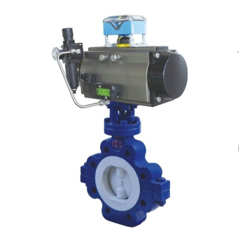

PTFE Lined Pneumatic Lug Butterfly Valve
The PTFE lined pneumatic lug butterfly valve is a fluoropolymer-lined isolation valve built in a lug-type body and driven by a pneumatic actuator for automated on-off duty in corrosive chemical, pharmaceutical, electroplating, pulp and paper, and water-treatment branches. Trekre Valve manufactures this assembly at our Wuxi facility with a split lug body, full lining of PTFE, PFA or FEP on all wetted surfaces, a stainless steel or lined disc, ISO 5211 actuator mounting, and lug ears. Any one-sided flange removal for maintenance requires confirmation of the exact valve model’s single-flange rating, permitted pressure direction, bolting arrangement and approved isolation procedure.
Compared with unlined ductile iron or carbon steel lug butterfly valves, the fluoropolymer lining isolates the body from acids, alkalis, chlorine-bearing media, and solvents that would attack bare metal. Compared with wafer-style lined pneumatic butterfly valves, the lug pattern provides independent bolting on each flange side, but the lug pattern alone does not establish suitability for dead-end service or permission to remove the downstream spool. Confirm the exact supplied valve’s documented single-flange rating, permitted pressure direction, bolting arrangement and isolation procedure for that duty. The valve is intended for shutoff and limited throttling; for continuous modulating control, confirm seat and actuator sizing against differential pressure and flow velocity.
Structure and working principle
The valve uses a two-piece lug body cast in WCB carbon steel or CF8/CF8M stainless steel, then lined by molding or paste-lining PTFE, PFA or FEP onto the bore, body flanges, and disc cavity surfaces. The split-body design allows inspection and replacement of lining components during overhaul without discarding the entire shell. The disc is typically 316 stainless steel with an encapsulating fluoropolymer layer, or a fully molded lined disc, rotating 90 degrees on a valve shaft. Confirm the shaft protection and sealing arrangement for the selected lining system.
Lug ears are cast or machined into both body flanges. Pipelines connect with through-bolts or cap screws depending on the lug style (semi-lug or full lug). Face-to-face dimensions follow common wafer/lug standards for the selected pressure class. At closure, the disc face compresses the seat ring molded into the body lining, forming a bubble-tight shutoff suitable for many chemical services when the lining grade matches the medium and temperature.
The pneumatic actuator mounts on the ISO 5211 top flange of the bonnet extension. Double-acting rack-and-pinion or scotch-yoke actuators use plant air (typically 3–7 bar filtered and regulated) to drive open and closed strokes. Single-acting spring-return versions return the disc to a defined fail position when air is lost. Optional Namur solenoid valves, air filter-regulators, and open/closed limit switches integrate with DCS or PLC panels. A positioner can be added where proportional throttling is required within the lined valve’s velocity and cavitation limits.
Some assemblies combine pneumatic automation with a manual path: a filter-regulator and worm-gear handwheel on the actuator allow local operation when air is unavailable during commissioning. Signal feedback accessories can be fitted on the actuator top works for remote position indication.
Drive, connection, and sealing
Drive: Pneumatic double-acting or spring-return actuator; optional handwheel override and 4–20 mA positioner.
Connection: Lug-type between flanges; drilling per ANSI Class 150, JIS 10K, EN PN10/PN16 or DIN equivalents as specified on the order.
Sealing: Fluoropolymer seat integrated with body lining (PTFE, PFA, FEP); stem sealing with compatible packing and lined stem sleeve.
Body materials: WCB, CF8, CF8M with full fluoropolymer lining on wetted areas.
Disc: 316SS with fluoropolymer encapsulation or molded lined disc.
Nominal size and pressure class
Common production spans nominal diameters from DN50 to DN600 (NPS 2 to 24) for lined lug service. Larger sizes are available by project review. Pressure-temperature limits follow the lining grade and body rating; typical catalog ranges include EN PN10 and PN16 or ANSI Class 150 lug configurations. Always confirm allowable pressure versus temperature for the specific fluoropolymer (PTFE, PFA, FEP) on the data sheet for your medium.
Applicable media and industries
Typical applications include hydrochloric acid dilution lines, sulfuric acid transfer within lining temperature limits, sodium hypochlorite dosing, caustic soda circuits, brine and seawater with lining suitability, pharmaceutical ingredient transfer, and aggressive wastewater streams. The valve is not intended for abrasive slurry with high solids content unless a special disc and seat design is specified. Vacuum service requires a project review of lining adhesion and disc stability.
Product parameters (reference)
| Valve type | PTFE / PFA / FEP lined lug butterfly valve |
| Actuation | Pneumatic double-acting or spring-return; ISO 5211 mounting |
| Body | WCB or CF8/CF8M, split lug pattern, full fluoropolymer lining |
| Disc | 316SS lined or molded fluoropolymer disc |
| Lining options | PTFE, PFA, FEP (medium and temperature dependent) |
| Nominal size | DN50–DN600 (NPS 2–24) typical; consult factory for other sizes |
| Pressure class | PN10, PN16, Class 150 lug (as ordered) |
| Operating temp. | Per lining grade; confirm on technical agreement |
| Leakage class | Per test procedure on the inspection document |
| Accessories | Solenoid valve, filter-regulator, limit switches, positioner, manual override |
Installation and maintenance notes
Install the valve with pipeline supports so dead weight does not load the lug ears unevenly. Use gaskets compatible with fluoropolymer faces; avoid fiber gaskets that can extrude into the lining bore. Tighten flange bolts in a cross pattern to the torque recommended for the flange rating and gasket type. Before first operation, cycle the valve partially open and closed with air connected to verify actuator stroke and limit switch settings.
Do not use the valve to pull misaligned piping into position; misalignment can crack lining at the flange transition. For maintenance, follow the approved isolation, depressurization and disassembly procedure for the exact valve. Any one-sided piping removal requires confirmation of the supplied valve’s documented rating, lug drilling and fastener arrangement; do not infer the removal sequence from the lug body style alone. Inspect lining for blistering, cracks, or discoloration at the disc edge and seat land. Replace stem packing using materials specified for fluoropolymer-lined valves. Store spare discs and seats in a clean, dry area away from sharp tools that could score the sealing surface.
Selection checklist for buyers
Provide medium composition and concentration, minimum and maximum temperature, design pressure, nominal size, flange standard and drilling, required fail mode (fail open, fail closed, or double-acting), control signal (on-off solenoid or 4–20 mA), enclosure and area classification if applicable, and lining preference (PTFE, PFA, FEP). Trekre Valve engineers can match actuator torque to disc diameter and differential pressure and confirm face-to-face dimensions for your piping specification.
Common questions
When should PTFE lining be chosen over PFA or FEP? PTFE offers broad chemical resistance at moderate cost; PFA and FEP can improve permeation resistance and high-temperature stability in specific services. The choice depends on medium, temperature, and prior plant experience with the same lining grade.
Can this valve replace a manual lined lug valve on existing bolt holes? Lug valves of the same nominal size and pressure class usually match existing flange drilling, but verify face-to-face length and actuator height clearance before ordering.
Is modulating control acceptable? Lined butterfly valves can throttle within limited opening angles; high velocity and cavitation can damage lining at small openings. Size the valve and actuator for the required range and consult factory guidance for continuous modulation.
How is shutoff leakage verified? Factory testing follows the agreed standard and leakage class on the inspection document; field acceptance should use the same procedure and medium-appropriate safety precautions.
Final dimensions, materials, actuator model, lining grade, and test requirements are confirmed on the Trekre Valve technical agreement, nameplate, and inspection documents for each order.