

The Pneumatic angle control valve is composed of membrane actuators and angle globe valve body, which can be adjusted proportionally through a 4-20ma analog signal with a positioner.
Pneumatic angle control valve
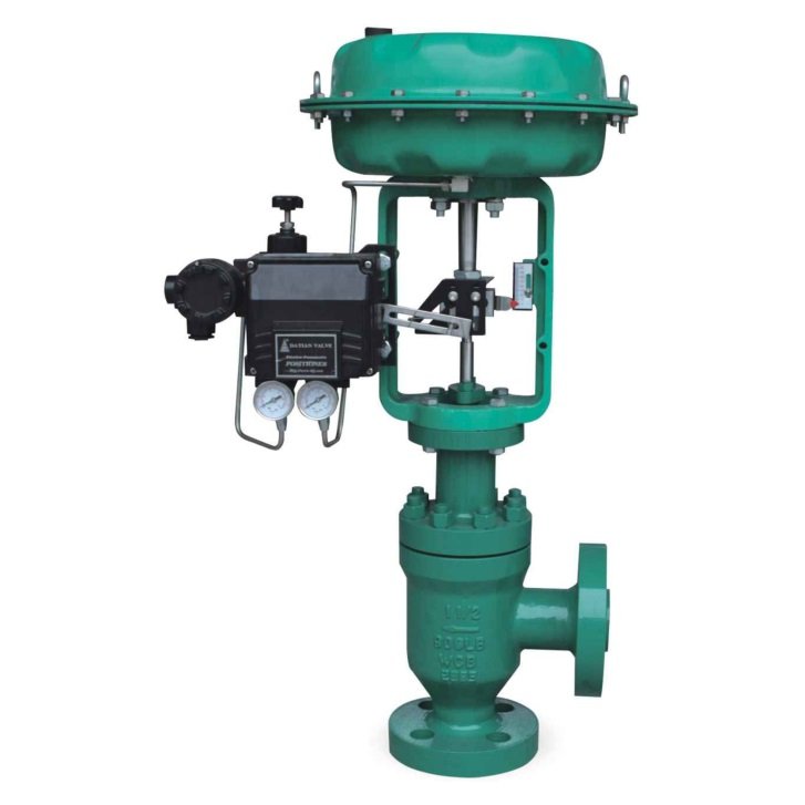
The pneumatic angle type control valve adopts a top guide structure and is equipped with a multi-spring pneumatic actuator. It has the advantages of compact structure, light weight, sensitive action, streamlined fluid channel, small pressure drop loss, large valve capacity, accurate flow characteristics, and convenient disassembly and assembly. Pneumatic angle control valves are widely used in precise control of gas, liquid and other media, and process parameters such as pressure, flow, temperature, and liquid level are kept at given values.
It is especially suitable for the adjustment of high viscosity, containing suspended solids and granular substances with small pressure difference between the valve and the valve with small leakage. It can avoid coking and blockage, and is convenient for self-cleaning and cleaning.
angle control valve Pneumatic actuators
Actuator Type: Diaphragm Actuator
Valve core: single seat, sleeve type
Size: DN20-DN200 NPS 3/4″-8″
Pressure class: PN16-PN100 Class 150-600
Connection: Flange-FF, RF, MF, RTJ Welding-SW, BW
Flange face to face: IEC 60534
Bonnet form: Standard type: (5℃-230℃)
Heat sink type: -45℃-350℃
Low temperature extension type: -196℃–45℃, bellows seal type, thermal insulation jacket type
Gasket: Metal clip graphite gasket
Frequently Asked Questions
What process data is needed to choose an angle control valve?
Provide the medium and solids characteristics where relevant, required flow range, inlet and outlet conditions and temperature. Request sizing and trim suitability for the selected configuration rather than selecting only by pipe size.
Does the pneumatic angle valve include the positioner I need?
Specify the required control and feedback interface, air-supply conditions and failure response. Ask for confirmation of the actuator, positioner and accessory scope; a general signal reference does not define every quoted assembly.
Which bonnet and connection arrangement should I request?
Provide the process conditions, piping end requirements and available installation space. Request the exact bonnet and flange or weld-end configuration on the order drawing rather than assuming all series options share the same limits.